Choosing the best Electrical Test Kit in 2026 depends less on the number of tools inside and more on the work it must support. A residential electrician checking outlets needs different functions from a technician troubleshooting motors or control panels. The right kit should make routine measurements clear, repeatable, and safe.
NFPA’s analysis of U.S. electrical-fire data from 2015–2019 estimates an annual average of 46,700 home structure fires involving electrical failure or malfunction. Those fires caused an estimated 390 civilian deaths and 1,330 injuries each year. This data does not show that a test kit prevents fires. It does underscore why dependable measurements and sound inspection practices matter. A meter that cannot verify voltage confidently is not a small inconvenience.
In this guide, we compare practical features: measurement range, probe quality, display readability, durability, and safety ratings. IEC 61010-related ratings and clearly stated measurement categories are important checks, but labels alone do not guarantee safe use. Match the instrument to the installation and follow its instructions. A bright screen helps in a dim service panel. So does a lead set that stays put.
There is no perfect bundle. More accessories can mean more cost, not better results. We also need to admit that product specifications do not tell the whole story; handling and service support matter. The recommendations ahead weigh those details alongside everyday usability, so readers can choose a kit suited to their tasks rather than the longest feature list.
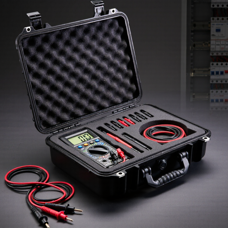
An electrical test kit is only suitable when its safety rating matches the circuit being tested. IEC 61010-1 sets general safety requirements for measurement equipment, while related IEC 61010 standards address measurement categories and specific instruments. CAT ratings describe expected transient overvoltage exposure, not overall product quality. CAT II generally covers plug-connected loads; CAT III applies to building distribution circuits; CAT IV covers the supply origin. Check the category and voltage rating together. A CAT III 600 V rating is not interchangeable with CAT III 1000 V.
For a kit, verify the meter, probes, leads, and accessories individually. The complete setup is limited by its lowest-rated component. Look for intact insulation, finger guards, clear markings, and instructions matching the intended work. A higher CAT rating is not a substitute for correct procedures or training. Labels can be easy to misread, especially in a dim panel room; pause and confirm them before connecting anything. That small delay matters.
Tips: Match the CAT category and voltage to the circuit location, then inspect every lead for cuts or loose fittings. Choose test functions you actually need, such as voltage, continuity, or current. Never assume an accessory shares the meter’s rating.
When choosing an electrical test kit in 2026, compare measurement category and voltage together. CAT III 1000 V and CAT IV 600 V describe different working environments, not a simple quality ranking. The category indicates the expected transient exposure; the voltage rating sets the permitted working voltage within that category. A higher voltage number alone does not make an instrument suitable everywhere.
CAT III instruments are intended for fixed installations, such as distribution panels, feeders, and building wiring. CAT IV instruments are designed for measurements closer to the installation’s origin, including service entrances and outdoor supply conductors. Those locations can expose equipment to stronger surges. That distinction matters. A CAT III 1000 V meter should not replace a CAT IV 600 V meter when the measurement point requires CAT IV protection.
Check the markings on the meter, probes, and leads before testing; the complete setup must meet the site’s category and voltage requirements. Look for clear ratings on each accessory, intact insulation, and finger guards that keep hands behind the probe barrier. A kit may advertise impressive voltage capacity, yet a lower-rated lead can limit the whole setup. I have seen this detail overlooked in tool comparisons, and it is easy to miss when equipment looks nearly identical. If the installation category is uncertain, pause and confirm it with qualified site guidance.
What Is the Best Electrical Test Kit in 2026?
Identify Installation-Test Functions Specified by IEC 61557
The best kit is the one that covers the tests your installation requires. IEC 61557 describes instruments for checking protective measures in low-voltage systems. Relevant functions include insulation resistance, earth continuity, earth resistance, loop impedance, and residual-current device performance. Phase-sequence testing may also matter for three-phase equipment. Check the standard’s relevant parts and your local requirements before choosing a kit. A crowded feature list is not enough.
The U.S. Bureau of Labor Statistics recorded 145 fatal work injuries involving exposure to electricity in 2022. This figure does not show that testing alone prevents incidents. It does reinforce why dependable measurements and safe procedures matter. Look for clear test limits, suitable measurement categories, documented calibration, and readable results. In practice, a tester must also fit the job: a site electrician checking a distribution board needs different functions from someone testing a single circuit. Even a well-equipped kit can leave gaps.
Tips: Match each test to the installation’s protective measure, then verify the instrument’s range and stated accuracy. Inspect leads before use, record results, and follow the manufacturer’s procedure. A quick check can miss a poor connection. Reflect on what the readings cannot prove, too.
| Test function | Relevant IEC 61557 part | What it checks | Useful kit-selection criteria | Typical relevance |
|---|---|---|---|---|
| Insulation resistance | IEC 61557-2 | Measures insulation resistance in de-energized circuits to help assess insulation condition. | Check that the tester provides the test-voltage settings and measurement range required for the intended installation and applicable test procedure. | Core function for installation verification and maintenance. |
| Continuity and resistance of protective conductors and bonding connections | IEC 61557-4 | Measures low resistance in earth connections, protective conductors, and equipotential bonding connections. | Look for a dedicated low-resistance continuity function, suitable test leads, and a method for compensating lead resistance where required. | Core function for checking protective-conductor and bonding paths. |
| Loop impedance | IEC 61557-3 | Measures the impedance of fault-current loops, supporting assessment of automatic disconnection by protective devices. | Confirm compatibility with the system and protective devices being tested; an RCD-compatible loop-test method may be useful where applicable. | Core function for many low-voltage installations. |
| Earth electrode resistance | IEC 61557-5 | Measures resistance to earth using methods appropriate to the electrode arrangement and test conditions. | Check which measurement methods the instrument supports and whether the required leads or auxiliary electrodes are available. | Important where the installation relies on an earth electrode. |
| RCD effectiveness testing | IEC 61557-6 | Tests residual current devices used in TT and TN systems as part of assessing protective measures. | Verify support for the RCD types and test procedures relevant to the installation; check that trip-time and, where applicable, trip-current tests are available. | Core function when residual current devices form part of the protection scheme. |
| Phase-sequence indication | IEC 61557-7 | Indicates phase sequence in three-phase systems. | Check that the tester identifies phase rotation clearly and is suitable for the system voltage and measurement conditions. | Useful for three-phase installation checks and equipment connection work. |
| Insulation-monitoring device testing | IEC 61557-8 | Addresses equipment for testing insulation-monitoring devices used in IT systems. | Choose this function when the work specifically involves IT systems and their insulation-monitoring devices. | Specialized; not required for every general installation test kit. |
| Insulation-fault location | IEC 61557-9 | Addresses equipment for locating insulation faults in IT systems. | Check compatibility with the IT system and fault-location method in use; this is usually a specialist requirement. | Specialized maintenance and fault-finding in IT systems. |
| Combined measuring equipment | IEC 61557-10 | Covers combined equipment used to test, measure, or monitor protective measures in low-voltage distribution systems. | For a general-purpose kit, compare the included functions against the tests actually required; a combined instrument does not necessarily include every function in the IEC 61557 series. | Relevant when selecting a multifunction installation tester. |
Selection guidance: There is no single best kit for every job. Prioritize the functions required by the installation type, local rules, and test procedure, then confirm the instrument’s applicable IEC 61557 conformity documentation, measurement ranges, accessories, and calibration status. IEC 61557 describes instrument requirements; it does not replace the applicable installation verification rules.
Match Voltage, Continuity, and Insulation Tests to Field Tasks
The best electrical test kit is the one that fits the work, not the one with the most functions. For checking a supply or confirming a circuit’s operating voltage, choose a meter with suitable measurement ranges and clearly rated leads. A stable display and a comfortable grip matter when you are working beside a crowded panel. Check the tool and leads for damage before each use. Small details count.
Continuity testing helps locate broken conductors, loose connections, or failed fuses, but test only on de-energized circuits. Verify the circuit is isolated and confirm the tester works before and after checking for voltage.
Insulation resistance testing serves a different task: it can reveal deteriorated insulation in cables or equipment. Disconnect sensitive electronics first, and follow the test instrument’s instructions. I still pause before insulation tests; it is easy to overlook a connected component.
Tips: Match the kit’s voltage and safety ratings to the site and task. Keep leads clean, and replace cracked insulation promptly. Record readings with the circuit, test conditions, and date, so future checks have useful context. If a reading seems unusual, stop and verify the setup rather than trusting one number. That extra check can feel slow. It is usually worth it.
Choosing the best electrical test kit in 2026 means matching its safety ratings to the work environment. A kit used on building circuits needs suitable measurement-category ratings for the expected installation, not merely a high voltage number. Check the meter, leads, and probes; the weakest component can limit the whole setup. Look for intact insulation and clear rating marks. Small details matter.
Accuracy deserves more than a glance at display resolution. A screen showing extra digits does not guarantee a more accurate reading. Compare the published accuracy specification across the voltage and current ranges you actually use. For drives or other equipment with changing waveforms, true-RMS measurement may be useful. A steady reading can still be misleading.
Calibration needs depend on use, storage, and measurement risk. Frequent field work or critical readings may call for shorter verification intervals than occasional checks. Look for documented calibration procedures and traceable records, then follow the kit maker’s stated requirements. Keep the latest certificate with the equipment. It is easy to postpone this task; that is worth rethinking. A simple check against a known reference can help reveal drift, but it does not replace formal calibration when that is required.
Compare safety ratings, measurement accuracy, and calibration needs before choosing a kit.
Safety comparison: IEC 61010-1 specifies impulse withstand levels of 2.5 kV for CAT II, 4 kV for CAT III, and 6 kV for CAT IV at a 300 V rated working voltage. These are category reference values—not scores for specific kits. Check the ratings on the instrument and its test leads. Accuracy specifications and calibration intervals vary by model; compare the stated measurement accuracy and follow the manufacturer’s calibration guidance.
We are here to help you with all your queries and concerns, just write to us using the below form and we will get back to you as soon as we can.