
In 2026, choosing a Lightning Arrester requires more than comparing discharge-current ratings. Modern installations combine rooftop solar, battery systems, data networks, and sensitive control equipment. Each addition changes the path that surge energy may follow. A device protecting a factory motor may not suit a hospital imaging room. The right choice begins with the building’s voltage system, earthing arrangement, exposure level, and equipment value. It also considers temporary overvoltage, regional lightning activity, and available maintenance quality. Small details matter. A loose bonding conductor can undermine an otherwise capable arrester.
This guide translates engineering practice into practical decisions. It explains key ratings, protection zones, response behavior, coordination, installation distance, and inspection needs. It also highlights evidence that deserves attention, including test reports, manufacturer documentation, and certification from recognized bodies. Field experience shows that selection errors often come from incomplete site information, not difficult mathematics. That is easy to overlook. No method is flawless. Local conditions, aging components, and undocumented modifications can change the risk after installation. Readers should verify recommendations against current standards, project specifications, and advice from qualified electrical professionals. A careful review of cable routing and bonding may reveal more than a glossy product brochure. The goal is not to choose the strongest-looking device. It is to choose a coordinated, maintainable solution that limits dangerous surge energy without creating new weaknesses.
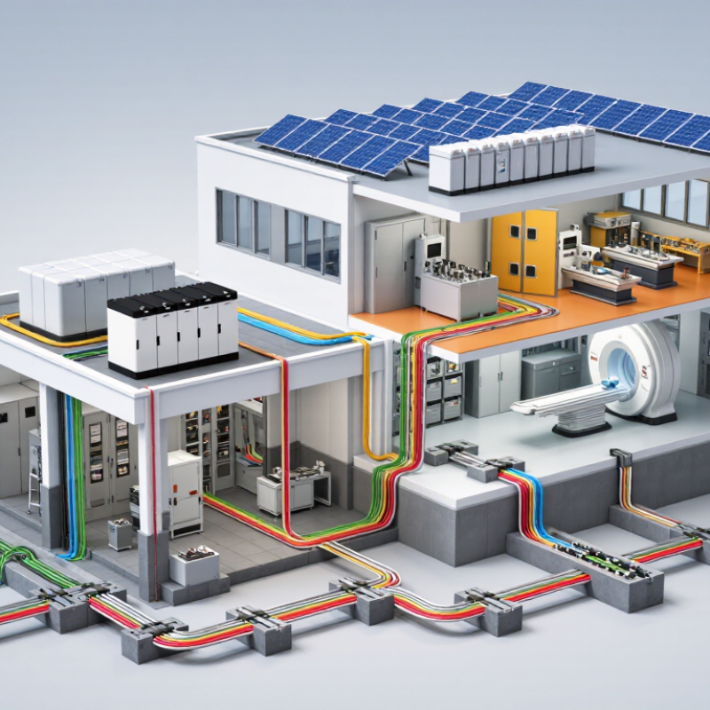
A lightning arrester protects electrical equipment from dangerous transient overvoltages. It does not stop lightning from forming. Instead, it provides a controlled path toward earth when voltage rises sharply. Modern arresters commonly use metal-oxide varistors. These components remain highly resistant during normal operation. During a surge, their resistance drops within microseconds. The surge current then flows away from transformers, switchgear, cables, and control systems.
Selection should begin with the system’s maximum continuous operating voltage. The arrester’s voltage rating must suit the network, grounding method, and temporary overvoltage conditions. Insulation coordination matters too. A device with insufficient discharge capacity may fail during repeated or high-energy surges.
Check nominal discharge current, residual voltage, energy class, housing protection, and pollution resistance. Installation location is equally important. Long connecting conductors can add inductive voltage and weaken protection. Keep the path short, straight, and properly bonded.
Field inspections often reveal a simple problem: the arrester is suitable, but poorly installed. That detail is easy to overlook. Inspectors should check leakage current, grounding continuity, thermal disconnection, and signs of moisture or cracking. Remote monitoring can help identify aging before failure, although it is not a substitute for testing. No selection is perfect. Lightning exposure, soil conditions, and equipment sensitivity can change over time. A careful design review should question old assumptions, especially after network expansion or unusual surge damage.
Selecting a lightning arrester starts with the electrical system, not the product catalogue. Confirm the highest system voltage, grounding method, frequency, and expected temporary overvoltage. The arrester’s continuous operating voltage must withstand normal conditions without excessive leakage current. Its rated voltage should also suit fault events and switching surges.
Check the nominal discharge current and energy capability for the installation. A substation near overhead lines may face repeated, high-energy impulses. Cable-connected equipment may require closer coordination and a lower protection level. Compare the arrester’s residual voltage with the insulation level of transformers, switchgear, and cables. IEC 60099-4 or applicable national standards provide useful testing references. Field experience matters here. A correct calculation can still fail when cable length is ignored.
Environmental conditions often decide service life. Record altitude, ambient temperature, humidity, pollution, salt exposure, ultraviolet radiation, wind, and seismic risk. Coastal air can accelerate contamination and surface leakage. Dusty industrial sites may need a longer creepage distance and careful washing plans. Sealing quality is critical in wet locations. Small details matter.
Tips: Keep the connection leads short and straight. Inspect grounding joints for corrosion. Check spacing before installation. Review future load changes, too. I once trusted a clean indoor specification for a semi-open site; that assumption needed rethinking. Reliable selection includes installation records, maintenance access, and periodic thermal or visual inspections.
How to Choose a Lightning Arrester in 2026?
Matching an arrester to system voltage starts with the grounding method. For a 13.8 kV solidly grounded system, nominal phase-to-ground voltage is approximately 7.97 kV. However, engineers must check maximum operating voltage, not only the nameplate value. The arrester’s continuous operating voltage, or Uc, should remain above sustained phase-to-ground voltage. IEEE C62.22.1 recommends reviewing temporary overvoltage duration before selecting Uc and rated voltage, Ur.
Grounding changes the risk significantly. Solidly grounded networks usually limit healthy-phase voltage during a fault. Ungrounded, resistance-grounded, or resonant systems can produce higher temporary overvoltages. A rating that works on one feeder may fail on another. It happens.
NOAA’s National Severe Storms Laboratory estimates about 25 million lightning flashes occur annually in the United States. That exposure supports careful protection coordination, especially at substations and long overhead feeders. CIGRE Technical Brochure 549 emphasizes energy capability, discharge current, and system fault conditions during arrester selection. Check the manufacturer’s thermal stability data against the calculated TOV curve. Also verify insulation coordination under IEC 60099-4. My early mistake was treating Ur as a simple voltage label. It is not. Cable length, transformer impedance, grounding resistance, and local lightning density still require site-specific review.
Choosing a lightning arrester starts with the installation location. At a utility entrance, select a high-energy metal-oxide arrester with suitable continuous operating voltage. IEC 62305-1 uses 200 kA as the maximum lightning current for Protection Level I. That figure is severe, but real exposure varies by site. A transformer yard needs stronger energy handling than a small control panel. A Type 1 arrester handles direct or partial lightning currents. Type 2 protects downstream equipment from induced surges. Type 3 belongs close to sensitive devices. Layered protection is usually safer.
Material also matters. Metal-oxide varistors respond quickly and need no spark gap. Their leakage current can increase with ageing and heat. Porcelain housings offer strong mechanical performance, but they can break violently after failure. Polymeric housings are lighter and more resistant to contamination.
IEEE C62.11 evaluates arrester duty through discharge-current and energy tests. Still, test ratings are not field guarantees. Cable length, earthing resistance, and repeated surges can change the result. I would not choose by kV rating alone.
Tips: Check Uc against the highest temporary overvoltage, not only nominal voltage. Keep connecting leads short and straight. Place Type 1 protection at the incoming service, Type 2 near distribution boards, and Type 3 beside sensitive electronics. Record leakage current during maintenance. That small measurement may reveal ageing earlier than visual inspection. Recheck the selection after a transformer, cable route, or grounding system changes.
A reliable choice starts with the installation, not the product label. Identify the system voltage, grounding method, fault current, altitude, and pollution level. IEC 60099-4 provides a useful technical reference for metal-oxide arresters. Always verify the current edition and applicable national electrical codes. Independent test reports should come from accredited laboratories. Local utility requirements also matter.
Maintenance planning reveals long-term value. Inspect the housing for cracks, tracking marks, corrosion, and moisture entry. Check mounting bolts and conductor connections for looseness. A leakage-current monitor can reveal gradual deterioration, but it needs correct interpretation. Thermal imaging may expose abnormal heating during service. Record inspection dates, weather conditions, readings, and corrective work. Keep records accessible.
Small details matter.
A clean inspection report can still miss internal damage. In coastal or industrial areas, surface contamination may accelerate aging between scheduled visits. I would set inspection intervals from site conditions, then review them after the first operating year. That approach is less convenient, but often more realistic. Ask whether the arrester can tolerate temporary overvoltage and repeated lightning events. Confirm replacement access before installation. A low purchase price can become expensive when shutdowns, specialist labor, or unclear records appear later. Reliability depends on standards, installation quality, disciplined maintenance, and honest review of field experience.
We are here to help you with all your queries and concerns, just write to us using the below form and we will get back to you as soon as we can.