Choosing a Pet Flexible Circuit in 2026 means balancing bend life, electrical performance, cost, and production consistency. The wider market is growing: Grand View Research estimated the global flexible printed circuit board market at USD 26.02 billion in 2023, with an expected 8.2% compound annual growth rate from 2024 to 2030. This figure covers flexible circuit boards broadly, not PET circuits alone. Still, it signals rising demand for compact, lightweight interconnects in consumer electronics, automotive systems, and medical devices. The distinction matters.
A PET-based design can suit applications where thinness and controlled costs are priorities. But PET is not a universal substitute for polyimide. Temperature limits, copper adhesion, trace width, bend radius, and exposure to moisture all affect performance. A circuit near a warm battery or a frequently flexed hinge needs different evaluation from one mounted inside a stationary sensor. Look closely at the datasheet. Ask suppliers for test conditions, not just headline values. IPC-2223, the sectional design standard for flexible printed boards, can help teams assess design requirements; it does not certify a particular product. Compare documented bend-cycle results, dimensional tolerances, and sample inspection records. Then verify that the proposed stack-up matches the real operating environment. One detail is easy to miss: a promising prototype may not reflect production variation. The best choice is therefore not simply the cheapest PET film or the thinnest circuit. It is the construction supported by credible specifications, repeatable manufacturing evidence, and testing relevant to your application.
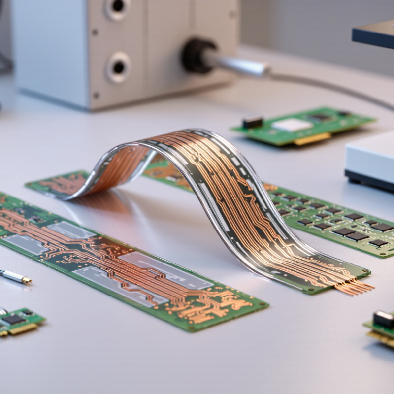
A PET flexible circuit uses a thin polyethylene terephthalate film as its insulating base. Conductive paths may be printed with conductive ink or formed from a bonded metal layer. The choice affects resistance, current capacity, and manufacturing cost. PET is lightweight and can suit compact controls, membrane switches, and simple sensor connections. It bends easily. Repeated bending is another matter.
Its key features include thickness, bend radius, trace spacing, and resistance to heat and moisture. A circuit folded around a small plastic enclosure may need a wider bend than its appearance suggests. Sharp creases can damage traces or weaken the bond between layers. PET generally handles less heat than some high-temperature flexible substrates, so check operating and soldering temperatures against the material specification. Details matter.
For a real design, inspect the circuit after bending it through its intended motion. Look for lifted edges, cracked traces, or changes in electrical resistance. Also consider cleaners, humidity, and the force applied by connectors. A lab test cannot perfectly reproduce every user’s handling. That limitation is worth admitting. Select the construction for the actual environment, not just the drawing or the lowest quoted price.
A PET flexible circuit should be specified around its real job, not just its outline. Record signal speed, current, voltage, minimum bend radius, and expected flex cycles. Also note whether the circuit sits near a warm battery, a sunlit window, or a cleaning fluid. These details change material and copper choices. Small details matter.
Temperature
Temperature needs careful interpretation. The Polymer Data Handbook, 2nd edition, places PET’s glass-transition range broadly around 70–80°C, depending on grade. That is not a safe operating-temperature rating. Above this region, stiffness and dimensional stability can change, so check the exact film data and test the assembled circuit. IEC 60216-1:2013 evaluates thermal endurance using time-to-endpoint measurements, rather than relying on one peak-temperature figure. Real fixtures can surprise you.
Mechanical conditions
Define mechanical conditions just as precisely: bend direction, radius, speed, and cycle count. IPC-2223D, the flexible-board design standard, treats bend performance as dependent on construction and geometry. A static fold and a moving hinge are different jobs. Measure the tightest radius on the actual enclosure, then test samples after heat and humidity exposure. One weak assumption is easy to miss: a room-temperature bend test may say little about a warm, repeatedly flexed circuit.
Comparing Materials, Circuit Designs, and Manufacturing Options
PET film is a practical choice for thin, lightweight circuits used in displays, sensors, and control panels. Compare film thickness, adhesive, and operating temperature against the device’s real conditions. PET generally handles less heat than polyimide, so soldering and nearby hot components need careful review. Check the supplier’s temperature limits, not just the material label. Small details matter.
Circuit layout affects reliability as much as the film itself. Wider traces can reduce resistance, while rounded corners help avoid stress points. For a circuit that bends repeatedly, confirm the bend radius and test it in the assembled product. A design that flexes once may fail after thousands of cycles. Static applications have different needs, and can often use simpler layouts. A neat drawing is not proof of durability.
Manufacturing options include etched copper circuits and printed conductive inks. Copper can suit finer traces and higher current, while printed circuits may fit simpler patterns or cost-sensitive runs. The right choice depends on trace spacing, electrical load, quantity, and inspection needs. Ask how prototypes are checked for shorts, opens, and alignment. Request samples made with the intended process. Real parts can expose awkward connector placement or unexpected stiffness. I would not assume the first design is the best; a modest layout revision may improve assembly and service life.
A PET flexible circuit supplier should be judged by process evidence, not a polished certificate wall. Prismark’s 2024 industry update placed global PCB production near US$73 billion in 2023; that broad figure is not PET-specific, but it shows the scale of a crowded supply chain. Ask for the certificate’s current validity, site, and manufacturing scope. ISO 9001 supports quality-system consistency, while IPC-6013 provides requirements for flexible printed boards. Neither proves that a particular PET design will meet your needs. Paper is not proof.
Review traceability records for PET film thickness, conductor adhesion, and dimensional stability after heat exposure. Ask suppliers to document pilot-lot yield, inspection methods, and corrective actions—not just their best sample. Run a pilot. Then compare measured results across batches. Capacity deserves the same scrutiny: request monthly output for the relevant line, current utilization, typical lead time, and backup plans for equipment downtime. A large factory-wide capacity number can hide a small PET line running near its limit. I would still question any unusually high yield claim without dated, product-specific records. That extra check takes time, but it can reveal gaps before volume orders begin.
How to Choose the Best PET Flexible Circuit in 2026
A prototype should be tested in the conditions where the circuit will actually work. Mount it on the intended surface, connect the real components, and check whether folds, adhesive edges, or nearby parts create stress. Measure electrical resistance before and after bending, and note any intermittent connections. Small details matter. A connector that fits on a flat bench may shift once the PET is curved. Record the bend radius, dimensions, and test conditions so results can be compared across revisions.
Reliability checks should reflect expected use, not just a quick visual inspection. Cycle the circuit through repeated bends, then inspect traces and connections under magnification. If the product may face heat or humidity, test representative samples in those conditions and check for lifting or resistance changes. A common mistake is approving a design after one successful sample. That can be misleading. Prototype testing has limits, especially when samples vary or the final assembly differs. Note what remains untested, adjust the design, and repeat the checks before selecting a circuit.
| Evaluation Area | Prototype Test | What to Measure or Check | Decision Criteria | Why It Matters |
|---|---|---|---|---|
| Mechanical fit | Install the prototype in the actual enclosure or assembly using the intended routing and fastening method. | Outline dimensions, connector alignment, hole locations, clearance, and interference with moving or sharp-edged parts. | Confirm the circuit fits without forced stretching, creasing, pinching, or obstructing other components. | Nominal drawing dimensions alone may not reveal enclosure tolerances or assembly conflicts. |
| Bend radius | Form the circuit around the smallest radius expected in the product and inspect it after forming. | Actual bend radius, copper-trace location, visible creases, and electrical continuity before and after bending. | Use the circuit supplier’s guidance for the chosen stack-up; do not treat one bend-radius value as suitable for every PET circuit. | Allowable bending depends on copper thickness, layer construction, trace position, and whether the bend is static or repeated. |
| Repeated flexing | Cycle the prototype through the product’s expected motion while monitoring critical conductors. | Number of cycles, bend radius, movement speed, and resistance or continuity changes during and after cycling. | Set the required cycle count and allowable electrical change from the intended service life and use conditions. | A circuit that survives one installation bend may not withstand repeated movement. |
| Electrical performance | Measure each net with a multimeter or four-wire resistance meter; test the assembled circuit under representative operating conditions. | Continuity, conductor resistance, voltage drop, signal behavior, and intermittent opens during movement. | Compare results with the circuit design and application limits; investigate unexpected resistance changes or intermittent readings. | Trace length, width, copper thickness, connectors, and operating current all affect electrical performance. |
| Insulation and spacing | Inspect conductor spacing and test insulation between adjacent nets and between conductors and accessible conductive parts. | Clearance, surface contamination, shorts, and insulation resistance at a test voltage appropriate to the circuit. | Choose test voltage and pass limits from the product’s working voltage, safety requirements, and insulation design. | Voltage withstand and insulation requirements are application-specific; a generic test limit is not suitable for every product. |
| Temperature exposure | Expose the prototype to the temperatures and dwell times expected in storage, operation, and assembly. | Electrical continuity, dimensions, flatness, adhesion, and connector or component condition before and after exposure. | Use the selected PET film, adhesive, copper, and component specifications to define the temperature profile and acceptance limits. | PET film and bonding materials vary by grade, and the complete circuit is limited by its most temperature-sensitive material. |
| Humidity and environmental exposure | Run a project-defined humidity or temperature-humidity exposure, then inspect and electrically retest the circuit. | Corrosion, discoloration, delamination, leakage between nets, and changes in resistance or insulation. | Define exposure conditions and limits from the product environment; use a recognized environmental test method when required. | Moisture can affect exposed copper, adhesive interfaces, connectors, and insulation performance. |
| Adhesion and delamination | Inspect edges and bonded regions after forming, environmental exposure, and any assembly heating. | Lifted coverlay or film, bubbles, edge separation, and movement of bonded stiffeners. | Reject defects that expose conductors, reduce required insulation, or compromise mechanical support. | Bond integrity helps protect conductors and maintain stable connections throughout use. |
| Dimensional stability | Measure critical features before and after the relevant thermal or humidity exposure. | Overall length and width, hole or slot positions, connector pitch, and alignment to enclosure features. | Compare measured change with the assembly tolerances and the mating component requirements. | Small dimensional shifts can make fine-pitch connectors or fixed mounting points difficult to assemble. |
| Connector and contact reliability | Mate and unmate the intended connector or contact system, then test the connection electrically. | Contact alignment, insertion and retention behavior, contact resistance, and damage to exposed pads. | Follow the connector manufacturer’s mating limits and the product’s electrical requirements; inspect for pad wear or deformation. | Connector performance depends on the contact system and assembly process, not just the flexible circuit itself. |
| Assembly-process compatibility | Build a representative prototype using the intended soldering, bonding, or attachment process. | Process temperature and time, pad condition, component alignment, and post-assembly electrical function. | Verify the process stays within the documented limits of the PET film, adhesive, copper, and components. | Assembly heat or pressure can affect materials even when the unassembled circuit passes inspection. |
| Prototype decision | Review test results against the product requirements and record failures, revisions, and retest results. | Fit, electrical function, flex life, environmental response, assembly yield, and unresolved risks. | Select a design only when project-specific acceptance criteria are met and critical tests are repeatable. | A documented test plan makes comparisons between prototype revisions more reliable. |
Note: Acceptance limits should be defined for the intended application and confirmed against the specifications of the selected materials, connectors, and assembly process. No single test value or bend-radius rule applies to every PET flexible circuit.
We are here to help you with all your queries and concerns, just write to us using the below form and we will get back to you as soon as we can.