A roll thread machine forms external threads by pressing hardened dies against a rotating workpiece. Unlike cutting, it displaces metal instead of removing it. The blank enters between the dies, follows a controlled path, and leaves with a precise helical profile. No chips. A cleaner production floor.
Manufacturing engineer Robert H. Todd describes the principle clearly: “Thread rolling forms the thread by plastic deformation, rather than by cutting it.” This distinction explains why a roll thread machine can produce strong, consistent threads at high speed. Material fibers remain continuous around the thread crest and root. That can improve fatigue resistance, surface finish, and repeatability when the setup is correct.
The machine’s performance depends on several practical details. Die design must match the thread standard and blank diameter. Lubrication controls heat and friction. Alignment prevents tapered or incomplete threads. Operators also inspect pitch diameter, flank quality, and surface damage during production. A small setup error can multiply across thousands of parts.
The process is powerful, but not universal. Very hard materials may require special preparation. Brittle materials can crack instead of flowing. Even an experienced operator must verify results with gauges and dimensional measurements. That part is easy to overlook.
This guide explains what a roll thread machine is, how its dies shape metal, and why process control matters. It also examines machine types, operating steps, benefits, limitations, and common quality problems. Expect practical details, not just a polished description.
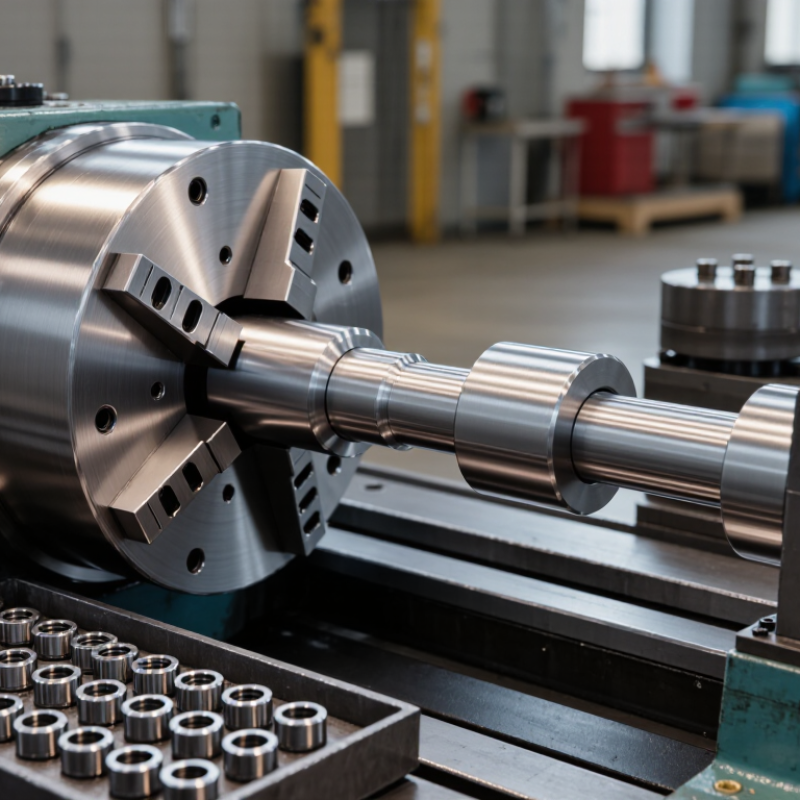
A roll thread machine forms external threads by pressing a cylindrical blank between hardened dies. The dies rotate or move linearly, forcing metal to flow into the thread profile. Unlike cutting, this process removes no chips. It reshapes the material instead. The result is a continuous grain pattern around the thread, which can improve fatigue resistance when the setup is correct. The machine’s purpose is clear: produce accurate threads quickly while reducing material waste and secondary finishing.
Thread rolling suits bolts, studs, shafts, and other cylindrical parts. ISO 68-1 defines the basic metric thread profile, while ISO 261 specifies metric thread series and sizes. These standards give operators measurable targets for pitch, flank angle, and diameter. Industry production studies often report cycle times of only a few seconds for high-volume rolled parts, although actual results depend on diameter, material, and die design. Metal-forming research also frequently reports material savings of roughly 15–25% compared with machining a thread from oversized stock. That range deserves caution. It is not universal.
In practice, an operator checks blank diameter, die alignment, lubrication, and thread gauge results. A small diameter error can create weak or oversized threads. Excessive pressure may damage the surface. The machine can look simple. It is not. A reliable process still needs inspection, tooling knowledge, and documented adjustments. My view is slightly imperfect: roll forming is often presented as automatically stronger, but poor setup can defeat that advantage.
Common ISO metric coarse-thread sizes and their standard pitches
A roll thread machine forms external threads by pressing hardened dies against a cylindrical workpiece and displacing the metal into the thread profile. Unlike cutting, thread rolling removes no material, which can improve surface finish and strengthen the thread through cold working. The chart shows standard ISO metric coarse-thread pitches for commonly used nominal diameters; these dimensions are thread specifications rather than machine-performance measurements.
A roll thread machine forms external threads by pressing hardened dies against a cylindrical blank. Unlike cutting, it displaces metal instead of removing chips. Pressure does the work. This process can produce strong, clean thread profiles with consistent dimensions. The machine frame supports every load, while the spindle or die head controls rotational movement. Guide rails keep the workpiece aligned during forming. Small alignment errors can create uneven pitches or damaged thread crests.
The dies are the machine’s working tools. Their profile determines the thread shape, diameter, and pitch. A feeding mechanism positions each blank between the dies and controls entry speed. Mechanical drives or hydraulic systems provide the necessary forming force. Hydraulic pressure is useful for adjusting force smoothly, but leaks can affect repeatability. The motor supplies rotation, while gears or belts transfer that movement to the die head.
A control panel manages speed, cycle timing, pressure, and emergency stops. Sensors may confirm part position before forming begins. Lubrication reduces heat and friction between the dies and workpiece. Guards protect operators from moving components and flying fragments. In practical use, operators inspect die wear, blank diameter, and thread gauges before production. I have found that clean dies matter more than expected. Even so, perfect settings do not guarantee perfect results; material hardness and temperature can still change the finished thread.
| Category | Main Component or Process | Primary Function | How It Works in the Thread-Rolling Process | Key Result or Consideration |
|---|---|---|---|---|
| Machine Overview | Roll Thread Machine | Forms external threads by cold-forming rather than cutting material away. | A cylindrical workpiece is pressed between hardened thread rolls. The rolls rotate and force the material into the required thread profile. | Produces threads with continuous grain flow, improved surface finish, and high repeatability when correctly set up. |
| Material Preparation | Workpiece or Blank | Provides the material that will be shaped into the finished threaded part. | The blank is supplied with a controlled diameter, length, chamfer, and material condition before entering the rolling zone. | Blank diameter and material ductility strongly affect thread height, pitch diameter, forming force, and dimensional accuracy. |
| Tooling | Thread Rolls | Transfer the thread geometry to the workpiece. | Precisely machined rolls engage the blank and displace surface material radially until the desired crest, flank, root, and pitch are formed. | Roll profile, pitch, hardness, alignment, and wear condition determine thread quality. |
| Tooling Support | Roll Spindles and Holders | Support and rotate the thread rolls while maintaining their position. | The spindles transmit torque from the drive system and hold the rolls at the correct center distance and angular relationship. | Rigid, accurately aligned holders help reduce vibration, taper, uneven loading, and premature tool wear. |
| Part Positioning | Work Rest or Support Blade | Supports the workpiece during rolling and helps establish its working position. | The workpiece rests against the support while the rolls apply forming pressure from above or from opposing sides, depending on the machine design. | Correct support height and condition are important for concentricity and stable part handling. |
| Part Handling | Guide, Stop, or Feeding System | Positions the blank consistently and controls entry and exit from the forming area. | Manual, vibratory, bar-fed, or automated systems may present each workpiece at a repeatable location and orientation. | Consistent loading improves cycle-time stability and reduces defects caused by mispositioning. |
| Power Transmission | Motor, Drive, and Gear System | Supplies controlled rotational power to the roll spindles. | The drive system synchronizes roll speed and transfers torque required to rotate the tools and the workpiece through frictional contact. | Speed and torque must match the material, thread size, roll design, and forming method. |
| Force Application | Hydraulic, Mechanical, or Servo Slide | Moves one or more rolls into the workpiece with controlled force and position. | The slide closes the tooling around the blank, maintains forming pressure, and retracts after the thread reaches the required dimensions. | Controlled force and stroke help prevent over-rolling, incomplete thread formation, and workpiece distortion. |
| Machine Structure | Frame and Bed | Provides a rigid foundation for the rolls, drive system, slides, and support components. | The frame absorbs forming loads and keeps the working components aligned throughout the cycle. | Structural rigidity contributes to dimensional consistency, low vibration, and longer tool life. |
| Process Control | Control Panel and Sensors | Controls operating parameters and monitors machine status. | Controls may regulate cycle timing, roll movement, feed position, lubrication, guarding, and fault conditions. | Monitoring improves repeatability and helps detect abnormal pressure, position, speed, or safety conditions. |
| Cooling and Lubrication | Lubrication or Coolant System | Reduces friction and heat at the roll-to-workpiece interface. | Lubricant is delivered to the forming zone to support material flow and reduce adhesive wear on the rolls. | Proper fluid selection, filtration, and delivery can improve surface finish and extend tool life. |
| Safety | Guarding and Interlock System | Protects operators from rotating tools, pinch points, chips, and unexpected machine movement. | Enclosures, access doors, emergency stops, and interlocks restrict access to the forming area during operation. | Safety devices should remain functional and should not be bypassed during setup or production. |
| Operating Principle | Radial Thread Forming | Creates the thread by displacing material instead of removing it with a cutting edge. | As the rolls penetrate the blank, material flows outward and fills the spaces between the thread-forming ridges. | Because no chips are produced during forming, the process can offer efficient production and strong thread geometry. |
| Operating Principle | Through-Feed Rolling | Produces threads on suitable parts that can travel continuously through the rolls. | The workpiece enters one side of the rotating rolls and exits the other side after the thread profile has been formed. | Well suited to high-volume production of parts with consistent thread locations and accessible rolling areas. |
| Operating Principle | Infeed or Plunge Rolling | Forms a thread over a defined length while the workpiece remains in a controlled position. | The rolls move radially into the stationary or positioned workpiece and then retract after the forming cycle is complete. | Useful for shoulders, blind thread sections, or parts that cannot pass continuously through the tooling. |
| Quality Control | Thread Inspection | Verifies that the finished thread meets dimensional and functional requirements. | Inspection may include pitch diameter measurement, thread gauges, visual checks, surface inspection, and verification of thread length and location. | Regular inspection helps identify roll wear, incorrect blank size, misalignment, or unstable forming conditions. |
A roll thread machine forms external threads by pressing a cylindrical blank between hardened dies.
It does not cut a spiral into the surface. Instead, controlled pressure displaces metal radially, creating the thread profile through cold working.
The blank rotates while the dies move or remain synchronized. This process can produce stronger thread roots and smoother surfaces than many cutting methods.
The 2023 Fastener Industry Association technical guidance reports that rolled threads can improve fatigue performance when grain flow follows the thread contour. The report also notes that results depend heavily on material, die alignment, and lubrication.
A separate 2024 metal-forming market review estimates that cold-forming operations commonly achieve material utilization above 90%, although actual results vary by part design. That figure sounds impressive. It should not replace shop-floor measurement.
Operators first check blank diameter, hardness, and die condition. They then set pressure gradually and inspect pitch diameter, crest shape, and surface marks. One missed setting can ruin a full batch.
Tips:
Measure the blank before production. Keep dies clean and correctly aligned. Use calibrated gauges, not visual judgment.
Review ISO 898-1 requirements when producing mechanical fasteners. Record pressure, speed, lubricant, and inspection results.
My practical caution is simple: thread rolling is efficient, but it is not automatically defect-free. Thin sections may buckle, oversized blanks may overload the dies, and worn tooling can create defects that appear only after assembly.
A roll thread machine forms external threads by pressing a cylindrical blank between rotating dies. The dies displace metal instead of cutting it away. This process produces continuous grain flow and can improve thread strength. It also creates little scrap. The method works best with ductile materials, not brittle alloys.
Low- and medium-carbon steel are common choices for rolled threads. Austenitic stainless steel can work, but it needs controlled pressure and lubrication. Brass and aluminum require softer settings and careful die selection. The thread profile must match the product requirement. Common options include metric, Unified, trapezoidal, and pipe threads. A die designed for one profile cannot reliably produce another.
Machine settings determine quality. Operators adjust blank diameter, die spacing, rolling pressure, speed, feed length, and lubricant volume. A blank that is too large may cause torn crests. A small blank may create shallow threads. Alignment matters greatly. Even slight angular error can produce uneven flanks. Grand View Research reported that the global metal forging market reached about 41.2 billion dollars in 2023, with projected growth near 4.5% annually through 2030. That growth supports wider interest in efficient forming methods, although the figure covers more than thread rolling. In practice, I would verify every setup with a pitch gauge, diameter check, and sample inspection. Speed alone is not proof of quality.
A roll thread machine forms external threads by pressing hardened dies against a rotating workpiece. The dies displace metal instead of cutting it, creating a continuous grain flow around the thread. This method produces little scrap and supports fast, repeatable production. World Steel Association data shows that global crude steel output reached about 1.89 billion metric tons in 2023. That scale explains why efficient thread forming remains important across metalworking supply chains.
Industrial users apply roll threading to bolts, studs, screws, shafts, and tubular components. Automotive, construction equipment, energy, and general engineering plants commonly use the process. In practice, cycle speed is only one concern. Operators must match die geometry with material hardness, blank diameter, pitch, and required thread length. Poor alignment can create uneven crests or excessive forming force. Small errors matter.
Lubrication reduces heat and die wear, especially during continuous production. The machine frame must resist vibration, while sensors should monitor force, position, and feed consistency. ISO 898-1 provides mechanical property requirements for carbon and alloy steel fasteners, but compliance still depends on inspection and process control. A finished thread may look acceptable and fail under load. That is an uncomfortable possibility. Dimensional checks, hardness testing, and periodic profile inspection are therefore practical safeguards. Even experienced operators should question stable settings when material lots change.
We are here to help you with all your queries and concerns, just write to us using the below form and we will get back to you as soon as we can.