What Is a 5-Inch TFT LCD Module?

A 5-inch TFT LCD module is a compact visual interface found in industrial panels, medical instruments, vehicle systems, smart appliances, and portable equipment. Its practical appeal is clear: the screen fits comfortably in one hand, yet offers enough space for menus, charts, warnings, and touch controls. Typical modules use a 16:9 or 5:3 layout, LED backlighting, and resolutions such as 800 × 480 pixels. Some versions deliver 450 nits or more, helping operators read information under bright indoor lighting.

Industry data supports continued demand for small and medium displays. Omdia’s Display long-term demand forecast, 2024, tracks stable panel consumption across automotive, industrial, and embedded applications. The DSCC Quarterly Display Capex and Equipment Market Update also shows manufacturers continuing to invest in flexible and high-efficiency display production. These reports do not make every 5-inch TFT LCD module a guaranteed success. Application requirements still decide the outcome.

Display analyst David Hsieh has described the sector with a useful reminder: “The display is the most important interface between people and technology.” That idea is easy to test. A slow response, weak viewing angle, or dim backlight can frustrate users within seconds. Engineers therefore compare interface type, brightness, contrast, operating temperature, connector design, and long-term availability. A cheaper panel may appear attractive. It may also create higher integration costs later. This article examines how a 5-inch TFT LCD module works, where it performs best, and which technical details deserve closer scrutiny.
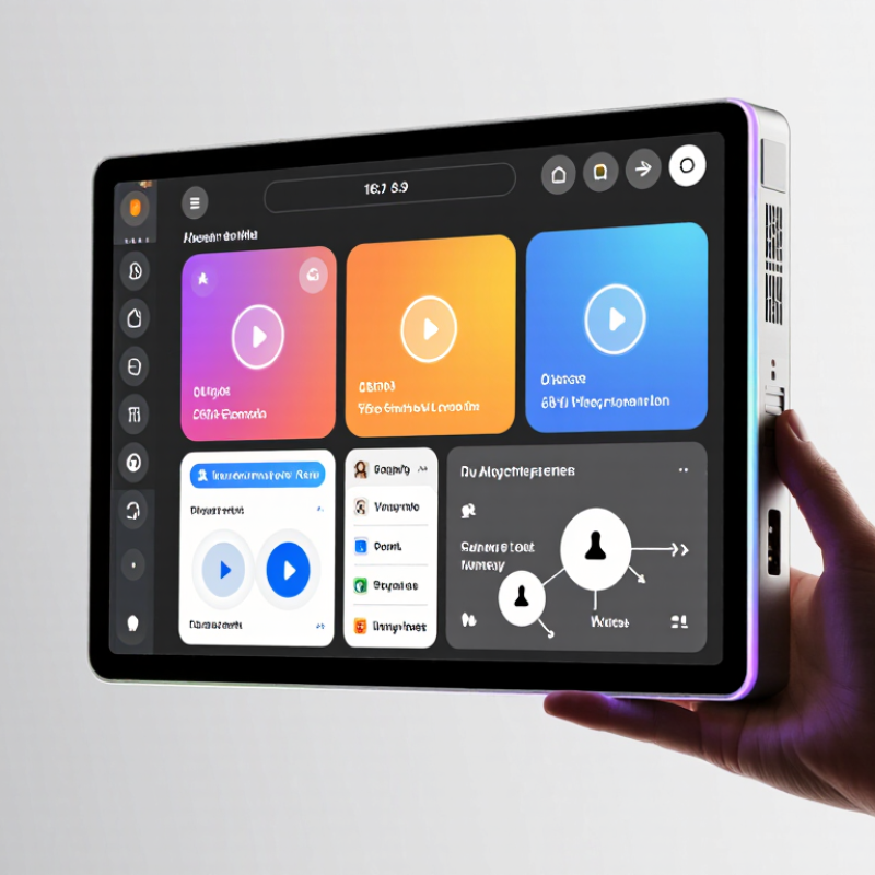
What Is a 5-Inch TFT LCD Module?

Definition and Core Purpose of a 5-Inch TFT LCD Module

What Is a 5-Inch TFT LCD Module?

Definition and Core Purpose of a 5-Inch TFT LCD Module

A 5-inch TFT LCD module is a compact flat-panel display measured diagonally across its visible area. TFT means thin-film transistor. Each pixel uses a dedicated transistor for faster switching, sharper images, and more accurate control than older passive-matrix displays.

Its core purpose is to present readable visual information in a limited space. A typical module may show menus, sensor values, maps, equipment status, or camera images. The screen usually includes an LCD panel, LED backlight, driver circuitry, and a flexible connection interface. Touch functionality is optional, not automatic. A project needs a separate touch layer or touch-enabled module.

Size alone does not define performance. Resolution, brightness, contrast, viewing angle, and color depth affect real usability. For example, a 5-inch screen with strong brightness may remain readable near a window, while a dim panel can fail outdoors. Interface selection also matters. RGB, SPI, and other interfaces require different controller resources and software timing.

Small details matter.

During integration, I check connector orientation, mounting holes, operating voltage, and backlight current before writing display code. A common mistake is choosing a panel by size alone. That approach can create poor viewing angles, unstable power behavior, or unreadable text. I also question whether high resolution is necessary, because it may increase processing demands without improving the user experience.

Key Components and Display Technologies

A 5-inch TFT LCD module combines a thin-film transistor backplane, liquid-crystal layer, polarizers, color filters, and an LED backlight. A 16:9 panel provides roughly 110 by 62 millimeters of visible area. Compact, but not simple. Omdia’s 2024 display forecast indicated that LCD panels would still represent more than 80% of global display unit shipments, showing their practical cost and supply advantages.

The driver IC controls each pixel through row and column signals. A flexible circuit connects the glass to the main board, while the backlight supplies uniform illumination from behind. IPS technology usually offers wider viewing angles than TN, although it may consume slightly more power. A capacitive touch layer adds another glass or film layer. That detail can reduce outdoor readability if the structure reflects too much light. Display Supply Chain Consultants reported strong demand for low- and mid-size display modules in embedded equipment, where brightness, lifetime, and stable interfaces matter more than extreme resolution.

Engineers should check the interface before choosing a module. RGB, MIPI, and SPI connections require different controller resources. A 5-inch panel may support 800 × 480 or 1280 × 720 resolution, but higher pixel density can increase memory and processing demands. In practical testing, viewing angle claims often look better indoors than outdoors. A 500-nit backlight may still appear weak under direct sunlight. Specifications help, but hands-on validation remains necessary.

How a 5-Inch TFT LCD Module Produces Images

What Is a 5-Inch TFT LCD Module?

How a 5-Inch TFT LCD Module Produces Images

A 5-inch TFT LCD module is a compact display assembly for embedded equipment. Its image begins with white light from a rear backlight. Behind the glass, a thin-film transistor controls each subpixel. Each pixel usually contains red, green, and blue subpixels. Tiny voltage changes alter liquid crystal alignment and light transmission. The process is physical, not software alone.

A display controller receives digital image data from the main system. It sends timed signals through the module’s interface. Driver circuits address individual rows and columns across the panel. For a bright red area, red subpixels transmit more light. Green and blue subpixels remain darker. Rapid updates make separate frames appear continuous. The backlight supplies the light that passes through these controlled layers. Without it, the image would be extremely dim.

In practical testing, viewing angle changes perceived contrast and color. Backlight unevenness can appear near the corners. Color accuracy depends on panel design, calibration, and viewing conditions. I would not judge a module from brightness alone. Refresh timing, pixel response, and connector signals matter too. A small wiring mistake can produce noise, wrong colors, or no picture. The result is not perfect. That limitation deserves attention during installation and evaluation.

What Is a 5-Inch TFT LCD Module? - How a 5-Inch TFT LCD Module Produces Images

Category Parameter Typical Value or Description Role in Image Production
Module Overview Display type TFT active-matrix liquid-crystal display Uses individually controlled pixels to form images.
Nominal diagonal size 5.0 inches, measured across the active display area Defines the approximate viewing size of the panel.
Common resolution 800 × 480 pixels Provides 384,000 individually addressable pixels.
Aspect ratio 5:3 for an 800 × 480 pixel array Determines the proportional shape of displayed content.
Approximate active area 108.0 mm × 64.8 mm for a 5:3 active area Indicates the illuminated image-forming region, excluding the bezel.
Approximate pixel pitch 0.135 mm per pixel Represents the center-to-center spacing of neighboring pixels.
Color depth Up to 24-bit RGB, or approximately 16.7 million colors Uses 8 bits each for red, green, and blue intensity levels.
Backlight White LED edge-light or direct-light arrangement Provides the light that passes through the liquid-crystal layer.
Image Formation Process 1. Image data input A controller sends pixel data through a display interface such as RGB or MIPI. Transfers color and brightness information to the module.
2. Timing control The timing controller coordinates rows, columns, synchronization, and refresh timing. Ensures each pixel receives the correct data at the correct time.
3. Row and column addressing Gate drivers select rows while source drivers apply voltage levels to columns. Addresses the targeted pixel locations in the active matrix.
4. Thin-film transistors Each subpixel uses a thin-film transistor and a storage capacitor. Holds the programmed voltage between refresh operations.
5. Liquid-crystal modulation Applied voltage changes the orientation of liquid-crystal molecules. Controls how much backlight passes through each subpixel.
6. RGB color filtering Each pixel contains red, green, and blue subpixels with fixed color filters. Combines different subpixel intensities to create the visible color.
7. Optical output Polarizers, alignment layers, color filters, and the backlight shape the emitted light. Produces the final image visible to the user.
Typical Electrical and Optical Characteristics Logic supply Commonly 3.3 V logic; exact limits depend on the module design Powers the interface and display-control electronics.
Viewing angle Typically specified separately for horizontal and vertical directions Describes image quality when viewed away from the center axis.
Response time Often approximately 10–30 ms for general-purpose panels Indicates how quickly pixels transition between brightness levels.
Refresh rate Commonly 60 Hz, subject to the controller and panel specification Determines how often the complete image is updated.
Touch function Optional resistive or projected-capacitive touch layer Adds user input capability but does not generate the image itself.

Note: Values shown are representative engineering references for 5-inch TFT LCD modules. Actual electrical, mechanical, optical, and interface specifications vary by module design.

Important Specifications and Selection Criteria

What Is a 5-Inch TFT LCD Module?

A 5-inch TFT LCD module measures about 5 inches diagonally across its active display area. It usually combines the panel, driver circuit, and connection interface in one assembly. The most important specifications include resolution, brightness, contrast, viewing angle, and color depth. A resolution such as 800 × 480 pixels can show clear menus, charts, and camera images. However, text may look less sharp than it does on a higher-resolution panel.

Selection should begin with the operating environment. For bright indoor or outdoor use, check the measured brightness in nits and confirm whether the display has optical bonding or an anti-glare surface. Review the interface carefully, such as SPI, RGB, or MIPI, because electrical compatibility affects development time.

I once underestimated cable length, and signal noise caused unstable images. That mistake was avoidable. Also verify the supply voltage, backlight current, touch technology, viewing direction, and active-area dimensions. Mounting holes and connector placement can decide whether the module fits a compact enclosure.

Tips: Compare real test data, not only catalog values. Test the screen at its lowest expected temperature and highest brightness setting. Check sunlight readability with the final cover installed. A larger resolution is not always better if the controller lacks processing capacity. Leave space for cables and ventilation. Small details matter.

Common Applications and Integration Considerations

What Is a 5-Inch TFT LCD Module?

A 5-inch TFT LCD module is a compact display assembly for showing text, images, menus, and live data. Its active area measures roughly five inches diagonally. Most models use a thin-film transistor panel, LED backlight, and a control interface. Common resolutions include 800 × 480 pixels, although specifications vary.

It fits well in industrial controllers, portable instruments, access terminals, medical equipment, and vehicle dashboards. A bright screen helps operators read measurements under factory lighting. A resistive touch layer may suit gloved users, while capacitive touch offers smoother interaction. The best choice depends on the environment, not appearance alone. Small details matter.

Integration begins with the enclosure. Leave clearance for the bezel, cable bend radius, mounting screws, and ventilation. Check viewing direction before fixing the panel. Colors can shift at steep angles. Power design also deserves attention: the backlight may draw more current than the display logic. Add suitable regulation, filtering, and protection near the connector.

Engineers should confirm the interface, timing, pin definition, and operating temperature early. Firmware must initialize the panel correctly and manage brightness without causing flicker. In prototypes, a connector can seem convenient, then become a vibration weakness. That lesson is easy to miss. Test the display with the final cover, gloves, sunlight, and actual cable length. Some designs pass bench testing but fail after heat builds inside the enclosure. Room for improvement remains.

Our dedicated sales and support staff are here to help you identify the ideal pump solution for your needs.

Contact Us